TN AppSvr110 I/O Auto Assignment Overview
Overview
IO auto assignment is new for Wonderware System Platform 2014 R2. The I/O auto assignment feature now provides an automated means of assigning application objects to devices, and of specifying input sources and output destinations on attributes.
IO auto assignment is ideally designed for PLCs which use a nonnumeric item reference or tagname such as ControlLogix. If the PLC uses numeric item references such as Modbus, then you will have to map those numeric references to alias in the DI object .
Application objects can be configured in such a way that the name of the object matches the name of the item in the PLC and the object attribute match the name of the PLC attribute. For instance, you have a user defined PLC item named PID_Pressure with attributes named PV, SP, CV, Kp, Ki, Kd and Auto. You can then create a UserDefined object in App Server named PID_Pressure then create attributes in this object to match the PLC attributes. Make sure to select the I/O feature from the list of available features for attributes that will be connected to live I/O.
Workflow
Basic steps needed to implement I/O auto assignment from start to finish in Application Server 2014 R2
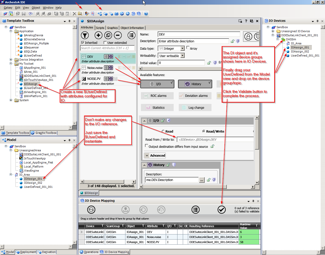
To prepare objects for I/O auto assignment
- Create a derived template from the $UserDefined base template and open it in the object Editor.
- Add attributes as needed. For each arrribute that requires input or output, click the I/O button.
- Change the I/O mode as required.
IMPORTANT – Do not alter the default I/O source string or you will not be able to sue auto assignment for the attribute. The default string indicates that auto assignment is not yet complete and the object is not yet linked to a PLC.
Also note that I/O Device Mapping will not over-write a manually entered I/O reference. If you have manually entered an I/O Reference and want to revert to Autobinding select the lightning bolt button which will appear to the right of manually entered references.
- Save and check in the template, then close the object Editor.
- In the Template Toolbox, create instances fromt eh UDO derived template. The instances appear under Model View under the Unassigned Area.
To configure DI objects and scan groups
- In the Template Toolbox, create a device integration object using any of the following templates;
$OPCClient
$DDESuiteLinkClient
$Redundant DIObject
The DI objects will appear under the “Unassigned Area” in the Model View and under the “Unassigned IO Devices” in the O Devices view.
- Add one more scan group to the DI object that you created in the previous step. The naming convention for the scan groups must confirm to the naming convention of the PLC with which you are connecting.
The scan groups will show as belonging to the DI object in the IO Devices view
Assign system and application (user created) objects to scan groups
Two Methods can be used to assign system and application (user created) objects to scan groups.
Method 1
- Create a new area and set it as the default area. Do not deploy the area yet.
- In the IO Devices view, drag and drop the area to a scan group.
- Create new application objects. As you create new objects, they will appear in the IO Devices view under the default area.
The IDE will complete the references for you.
-
If you need to change the scan group assignment for an object, drag and drop it to the new scan group.
Method 2
- Create a new area and assign it to a scan group.
- Create new application objects. These will appear in the “Unassigned” folder in the Model view.
- Assign the application objects to the area that was assigned to the scan group in step 1. All application objects assigned to
the area will inherit the area’s linkage to the DI object and scan group.
- If you need to change the scan group assignment for an object in the area, drag and drop it to the new scan group.
To validate I/O references (and override auto assigned values, if necessary)
- Open the IO Device Mapping view. This view opens automatically if you select an object, scan group, or DI object in the IO Devices view.
Each row in the IO Device Mapping table contains the IO reference for one attribute.
- Optional - Enter an override value for the attribute in one of the override columns.
Note – The DI Object.Scangroup Override column can only contain the DI object name and scan group name, separated by a period (.).
- Deploy the platform and associated DI objects.
- Client the Validate References button to check that communication is established with the PLC.
- Deploy the objects.